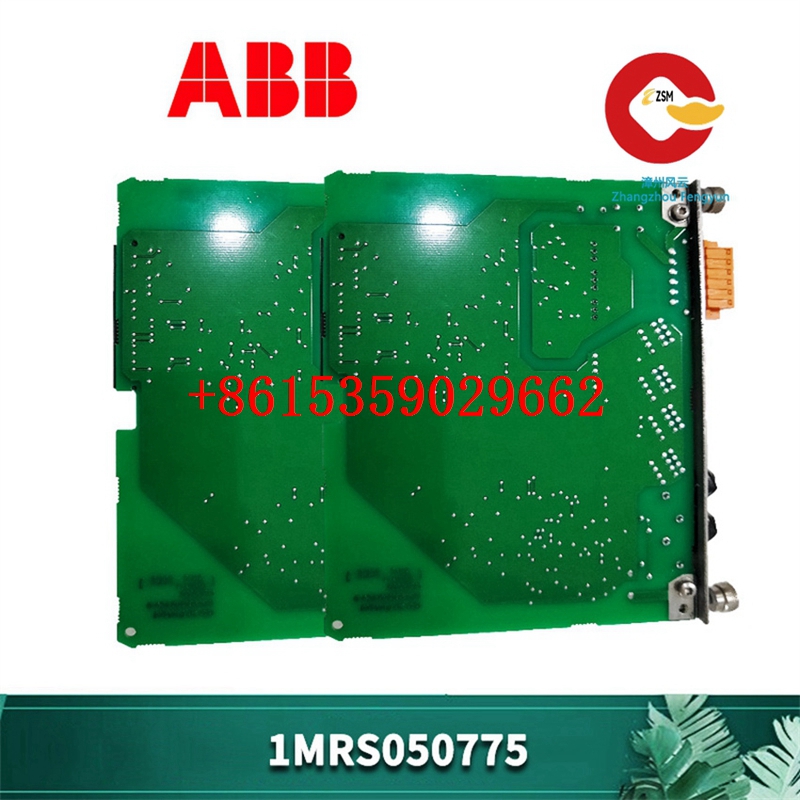
📘 GE DS215UPLAG1BZZ01A / DS200UPLAG1BEA — Module Overview
The GE DS215UPLAG1BZZ01A / DS200UPLAG1BEA is a high-performance I/O communication module designed for use in GE FANUC Mark V control systems. This module facilitates reliable data acquisition and signal processing for industrial automation applications, including turbine and generator control. Its robust design ensures long-term stability in demanding environments, with precise input handling, fault detection, and seamless integration into distributed control networks.

⚙️ Technical Specifications
| Parameter | Specification |
|---|---|
| Model | DS215UPLAG1BZZ01A / DS200UPLAG1BEA |
| Product Type | I/O Communication Module |
| Bus Interface | GE FANUC proprietary interface |
| Input Channels | 16–24 dry-contact inputs (depending on configuration) |
| Output Channels | 0 (input-only module) |
| Communication Protocol | LAN (Local Area Network) |
| Processor Types | LAN Control Processor (LCP), Drive Control Processor (DCP), Motor Control Processor (MCP) |
| Power Supply | 24 V DC integrated |
| Operating Temperature | -20°C to +60°C |
| Storage Temperature | -40°C to +85°C |
| Humidity | 5% to 95% non-condensing |
| Dimensions (W x H x D) | 167.65 mm × 111.15 mm × 45 mm |
| Weight | Approximately 0.5 kg |
| Mounting Type | DIN rail or panel mount |
| Certifications | CE, UL, RoHS |
🛠️ Key Features
- High-Density Input Support: Equipped with multiple dry-contact inputs, enabling connection to numerous field devices like switches, sensors, and relay contacts.
- Integrated Processing: Incorporates LCP, DCP, and MCP processors to manage control and communication tasks efficiently.
- Reliable Power Supply: Onboard 24 V DC power ensures stable operation without external supply complexity.
- Industrial Robustness: Designed for harsh environments with wide temperature tolerance and high humidity resistance.
- Seamless Integration: Compatible with GE FANUC Mark V systems and terminal boards for flexible system design.
- Fault Detection: Supports early detection of input and communication errors, enhancing system reliability.
🛠️ Installation and Maintenance Guidelines
Installation
- Power Off: Ensure the system is completely powered down before installation.
- Mounting: Secure the module on a standard DIN rail or designated panel slot.
- Input Wiring: Connect field device inputs according to system wiring diagrams.
- Power Verification: Confirm the onboard 24 V DC supply is correctly connected and stable.
- System Integration: Incorporate the module into the control system, verifying compatibility with other network components.
Maintenance
- Visual Inspection: Regularly inspect the module for physical damage, corrosion, or loose connections.
- Cleaning: Use a dry, lint-free cloth for exterior cleaning; avoid solvents or liquids.
- Input Verification: Test the functionality of input channels to ensure accurate signal acquisition.
- Diagnostics: Utilize system diagnostic tools to monitor performance and identify potential issues.
- Firmware Updates: Maintain up-to-date firmware to ensure compatibility with system upgrades and security improvements.
🔗 Additional Resources
🔄 Similar Products
| Model | Channels | Communication | Mounting Type |
|---|---|---|---|
| DS200UPLAG1BEB | 16 inputs | LAN | DIN rail |
| DS215UPLAG1BZC01A | 24 inputs | LAN | Panel mount |
| DS200UPLAG1BEC | 16 inputs | LAN | DIN rail |
| DS215UPLAG1BZD01A | 24 inputs | LAN | Panel mount |
| DS200UPLAG1BEF | 16 inputs | LAN | DIN rail |


