¥66,666.00 Original price was: ¥66,666.00.¥1,450.00Current price is: ¥1,450.00.
Product images and prices are not for reference. Please contact me for a quote!
🌍Country of origin: USA France Germany Estonia Norway UK
⌚Delivery date: in stock
🛠After-sales service: brand new with one year warranty
⚙️ Product Category: Module/Controller/Server/Motor/Touch Screen
🕰Warranty: 12 months/365 days
☎️ Please contact me: 15359029662 Ms. Amy Sun
📎Chinese official website: www.dcsplcabb.com
📩Email: geabbamy@gmail.com
💬Whatsapp: +86 15359029662


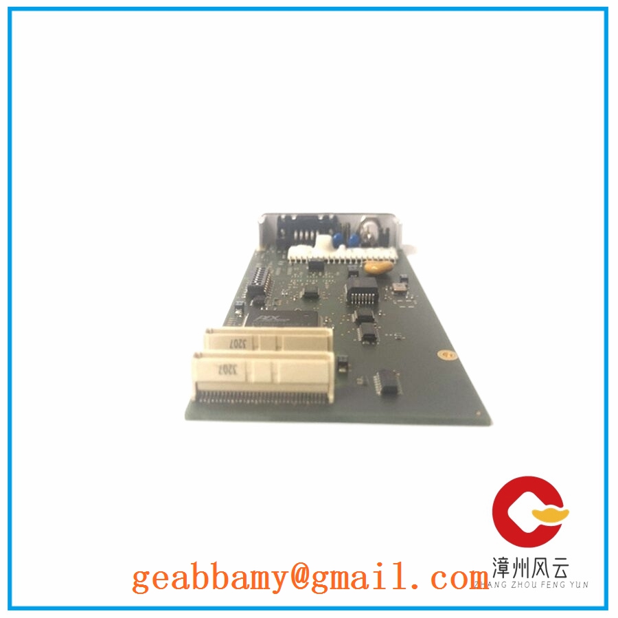
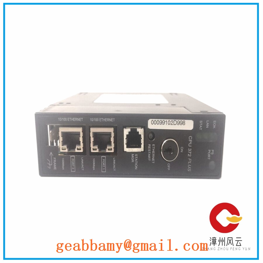
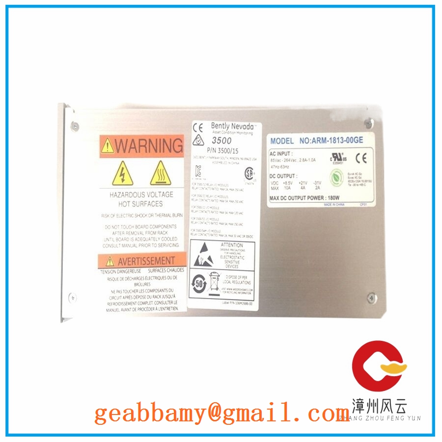
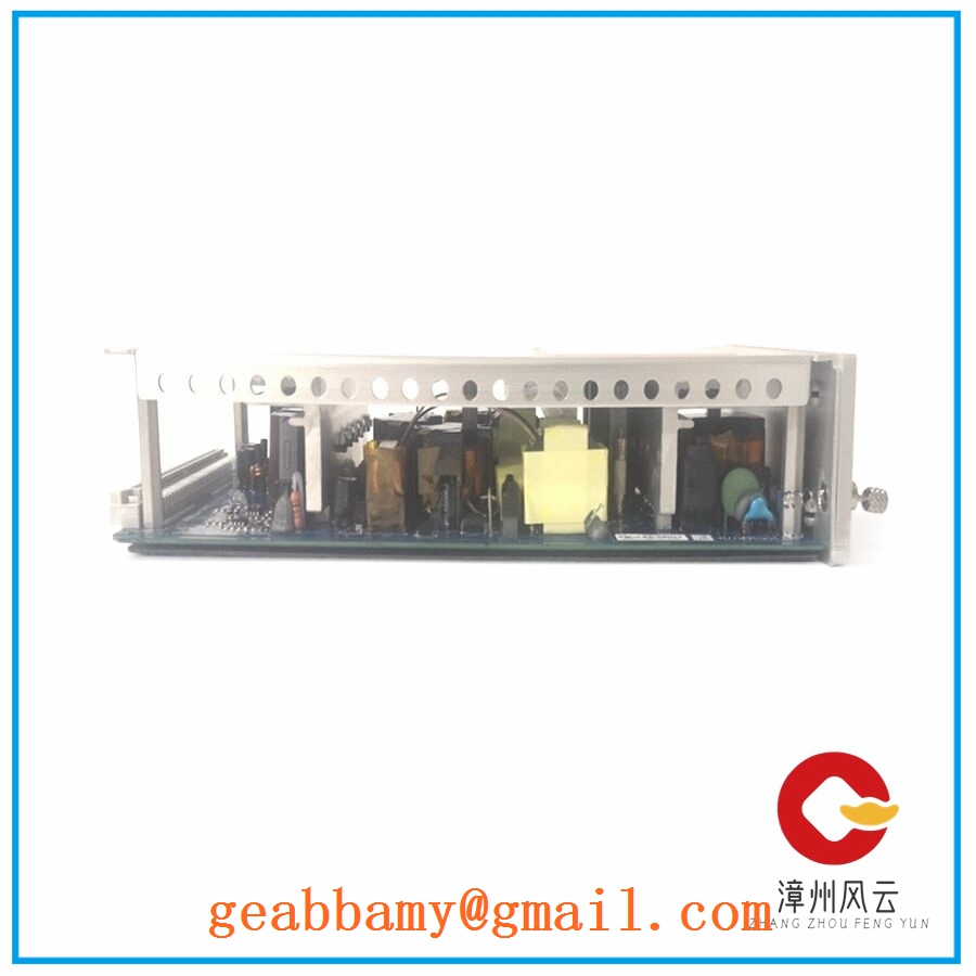
Model: IS200WETBH1B / IS200WETBH1BAA
Brand: General Electric (GE)
Series: Mark VI / IS200 Wind Energy Control
Core Function: Wind turbine top-box control and electrical interface
Product Type: Printed Circuit Board / Terminal Interface Board
Key Specs: WETB functional designation, Revision B, multiple board connectors
Supply Status: Available – confirm physical stock before ordering
Stock: Available upon confirmation
Warranty: Subject to supplier confirmation
Ship From: China
Manufacturer: General Electric (GE)
Model Number: IS200WETBH1B
Associated Assembly Number: IS200WETBH1BAA
Product Family: Mark VI Wind Control
Functional Acronym: WETB
Board Group: H1
Hardware Revision: B
Board Type: Wind Energy Top Box B printed circuit board
Connector Configuration: Multiple edge-mounted plugs and connectors
Internal Connectors: P1 (10-pin), P2 (6-pin), P3 (4-pin)
Electrical Interface: Verify supply and signal requirements against the applicable GE wiring documentation
Installation: Compatible Mark VI wind turbine control assembly, subject to revision verification
Technical note: Some third-party listings describe this board as an elevator control board, while other technical references identify it as a Wind Energy Top Box B board. The WETB designation and associated assembly should be verified against the original equipment documentation before purchase.
Contact Us Today+2
Wind turbine control systems depend on reliable electrical interfaces between the turbine controller, top-box assemblies, and field devices. When a WETB board develops relay, connector, or circuit faults, troubleshooting becomes more complicated because the problem may affect several connected control circuits.
Replacing the board is not simply a matter of matching the part number. Hardware revision, connector arrangement, wiring configuration, and the original turbine control application all need verification.
1. Wind Energy – Turbine Control Cabinets
Used within GE wind energy control assemblies. The board supports the electrical interface required by the associated top-box control architecture.
2. Wind Turbine – Electrical Interface Maintenance
Used during maintenance of WETB assemblies when connector damage, component failure, or circuit faults require board replacement.
3. Industrial Turbine – Control System Spare Parts
Maintained as a replacement component for existing GE Mark VI installations where the original hardware configuration must remain in service.
4. Turbine Retrofit and Maintenance Projects
Used when maintaining older turbine control equipment and preserving compatibility with existing field wiring and control hardware.
Illustrative engineering scenario, not a documented customer installation.
Background:
A wind farm maintenance team encounters intermittent control faults in a turbine top-box assembly. Initial checks identify abnormal electrical behavior around the WETB board.
Problem:
The maintenance team needs a replacement board but cannot risk installing a different hardware revision without checking the existing configuration.
Solution:
The engineering team performs the following checks:
Records the original board’s complete part number and revision.
Photographs connector positions and wiring arrangements.
Checks the associated GE control assembly documentation.
Compares the replacement board’s hardware markings.
Performs an appropriate bench inspection before installation.
Verifies field connections and controller diagnostics after replacement.
Result:
The replacement process follows a documented compatibility check rather than relying on model-number similarity alone. This reduces the risk of unnecessary wiring changes and commissioning delays.
The following distinction is important: related GE WETB boards are not automatically interchangeable.
| Original Model | Related Model | Compatibility | Main Difference | Required Action |
|---|---|---|---|---|
| IS200WETBH1B | IS200WETBH1BAA | Requires verification | Associated assembly designation | Compare nameplate and revision |
| IS200WETBH1BAA | IS200WETBH1BBA | Unconfirmed | Different board suffix | Verify GE assembly documentation |
| IS200WETBH1BAA | IS200WETBH1APR1 | Unconfirmed | Different revision designation | Check wiring and hardware compatibility |
| IS200WETBH1BAA | IS200WETAH1BB | Not a direct replacement | WETA rather than WETB | Different functional designation |
| IS200WETBH1BAA | IS200WETCH1AAA | Not a direct replacement | WETC board family | Different assembly function |
Related WETB part numbers appear in GE wind-energy component references, but that does not establish drop-in compatibility.
ConverterTec+1
Original-model replacement
If the existing board is IS200WETBH1BAA, prioritize the same complete part number and revision.
Before installation:
Compare the complete part number.
Check the board revision and assembly markings.
Verify connector positions and terminal assignments.
Confirm the original wiring diagram.
Check the associated controller configuration.
Important: No alternative listed above should be treated as a confirmed drop-in replacement without GE documentation or an approved application-specific cross-reference.
There is no verified price difference or engineering labor estimate for these alternatives. Obtain a project-specific quotation before approving a substitution.
| Fault Symptom | Possible Cause | Board Relevance | Quick Inspection | Recommended Action |
|---|---|---|---|---|
| Turbine control fault alarm | Board circuit failure | High | Review controller diagnostics | Inspect WETB board and connected circuits |
| Intermittent control signals | Loose connector or damaged circuit | High | Inspect connectors and wiring | Reseat connections under approved isolation procedure |
| No response from connected device | Field wiring or board interface fault | Medium | Check continuity and terminal assignments | Isolate the field circuit before replacing the board |
| Blown fuse | Short circuit or excessive load | High | Check fuse rating and downstream resistance | Identify the cause before replacing the fuse |
| Intermittent electrical operation | Connector oxidation or component deterioration | Medium | Inspect solder joints and connector contacts | Repair or replace after electrical testing |
| Communication alarm | Controller, network, or configuration fault | Low to medium | Review controller event logs | Check the communication path before replacing WETB |
1. Check the Power Supply
Use a calibrated multimeter to measure the specified supply terminals.
Compare the reading with the GE wiring documentation.
Check fuse continuity and signs of overheating.
Do not assume a 24 V DC supply. Confirm the actual electrical requirements for the installed assembly.
2. Inspect Connectors and Wiring
Check for loose plugs, bent pins, and damaged terminals.
Compare the wiring against the original connection diagram.
Inspect cable shields and grounding points.
3. Check the Controller Diagnostics
Retrieve the active alarm list.
Review the event history.
Identify whether the fault originates from the board or an external device.
4. Inspect the Board
Look for burned components, corrosion, cracked solder joints, and damaged connectors.
Check fuse continuity with power isolated.
Do not perform resistance measurements on an energized board.
5. Verify Hardware Revision
Compare the original and replacement board markings. A matching base model number alone does not establish electrical or functional compatibility.
A replacement board should pass a documented inspection before shipment.
Incoming Inspection
Verify the part number and serial number.
Check available original packaging and traceability documents.
Inspect for corrosion, scratches, discoloration, and previous repair marks.
Check supplied accessories and documentation.
Functional Testing
Inspect the PCB and connector condition.
Verify accessible electrical circuits.
Perform power-up and functional checks using an appropriate GE-compatible test setup.
Record applicable test results in a Test Report.
Electrical Testing
Check ground continuity where applicable.
Perform insulation and dielectric tests only when permitted by the manufacturer’s procedures.
Do not apply a 500 V insulation test indiscriminately to populated electronic circuitry.
Firmware and Configuration Verification
Record identifiable hardware revisions.
Document configuration jumpers and switches.
Back up available configuration information when applicable.
Final Inspection and Packaging
Obtain quality inspection approval.
Seal the board in an electrostatic discharge (ESD) protective bag.
Use bubble wrap and a suitable shipping carton.
Attach a QC inspection label and date.
Test photographs, videos, and inspection records can be provided when available. Actual test results should accompany the individual unit rather than being assumed from the model number.
Before installing the replacement:
One final piece of advice: Don’t replace an expensive turbine control board just because an alarm points in its direction. Check the power supply, field wiring, connectors, and controller diagnostics first. That simple sequence can save considerable commissioning time and prevent a second shutdown.