
Product Description
The STN Atlas GE 6010 G 203 is a dedicated printed circuit board used in the Atlas Elektronik GE 6010 marine speed log system. It is identified in the system documentation as the Bottom Echo Logic assembly.
The board processes bottom-echo detection signals used by the speed log to determine vessel speed relative to the seabed. It works as part of the larger GE 6010 electronic measurement system, coordinating echo detection and timing functions.
The GE 6010 G 203 is a system-specific marine electronic circuit board, not a general-purpose PLC or analog I/O module. It is intended for maintenance and replacement applications in compatible STN Atlas speed log equipment.
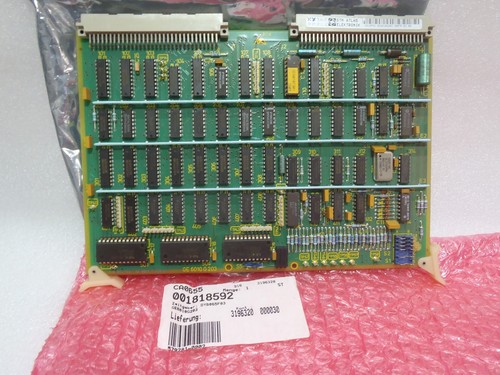
Product Parameters
- Brand: STN Atlas Elektronik
- Model: GE 6010 G 203
- Related Designations: GE 6010 T 203 1D / GE 6010 T 203 2D
- Additional Identification: DYB 065 F03
- Product Name: Bottom Echo Logic PCB
- Product Series: GE 6010 Marine Speed Log
- Equipment Type: Marine Speed Measurement System
- Functional Category: Bottom Echo Detection and Logic Processing
- Main Function: Processing bottom-echo detection and timing signals
- Indicator LEDs: CR9 (BT detection interval), CR10 (WT detection interval), CR11 (transmitter trigger signal)
- Jumper Configuration: S1 A-B and S2 A-B closed, as specified in the service manual
- Installation: Dedicated GE 6010 electronic equipment assembly
- PCB Material Marking: 94V-0
- Dimensions: Not verified
- Weight: Approximately 300 g, reported for this board family
- Country of Origin: Germany, as indicated on associated board listings; verify the supplied unit label
- Power Requirements: Refer to the GE 6010 equipment documentation
- Product Status: Legacy marine equipment spare part
- Product Condition: Confirm the condition of the supplied unit
Main Features
- Dedicated bottom-echo logic processing for the GE 6010 speed log.
- Supports bottom-echo detection and timing functions.
- Provides status indication through three onboard LEDs.
- Works with the associated GE 6010 transmitter, receiver, and interface assemblies.
- Designed for system-specific replacement and maintenance.
- Identified by the GE 6010 G 203 and related PCB markings.
Typical Applications
- Marine speed log systems
- Vessel speed measurement
- Bottom-track speed detection
- Ship navigation electronics
- Marine instrumentation maintenance
- Replacement of legacy STN Atlas electronic assemblies
- Shipboard speed measurement equipment servicing
Installation and Commissioning
- Verify that the original equipment uses the GE 6010 G 203 Bottom Echo Logic assembly.
- Compare all PCB markings, including GE 6010 G 203, GE 6010 T 203, and DYB 065 F03.
- Isolate the relevant equipment power supply before removing the original board.
- Record connector positions, jumper settings, and board orientation.
- Inspect the replacement PCB for corrosion, damaged components, bent pins, and contamination.
- Install the board in the designated GE 6010 equipment position.
- Check jumper switches S1 and S2. The service manual specifies the A-B positions as closed for normal operation.
- Restore power according to the manufacturer’s procedure.
- Observe CR9, CR10, and CR11 during the equipment’s operational test.
- Run the GE 6010 system self-test and check for bottom-echo logic fault codes.
- Verify bottom-track detection and compare the speed indication with an appropriate reference.
- Complete the operational test before returning the speed log to service.
Daily Maintenance and Care
- Inspect the PCB for corrosion, moisture, and contamination.
- Check connectors and board seating during scheduled maintenance.
- Monitor CR9, CR10, and CR11 during diagnostic testing.
- Check jumper positions against the original configuration.
- Inspect associated transmitter and receiver assemblies if bottom-echo detection is unstable.
- Keep the electronics enclosure clean and dry.
- Record board identification numbers and replacement dates.
- Maintain the original equipment’s configuration and service records.
Troubleshooting and Common Questions
Q1: What is the function of the GE 6010 G 203?
A: It is the Bottom Echo Logic assembly in the STN Atlas GE 6010 speed log system. It processes bottom-echo detection and timing signals.
Q2: What do the three onboard LEDs indicate?
A: CR9 indicates the bottom-track detection interval, CR10 indicates the water-track detection interval, and CR11 indicates the transmitter trigger signal.
Q3: Does the board require adjustment after replacement?
A: The GE 6010 DOLOG 20 service manual states that no adjustment is necessary after exchanging the timing assembly. It specifies checking that jumpers S1 A-B and S2 A-B are closed.
Q4: What may cause a bottom-echo logic fault?
A: Possible causes include a faulty GE 6010 G 203 assembly, associated signal interruptions, connector problems, or faults elsewhere in the transmitter and receiver signal path.
Q5: Can the GE 6010 G 203 replace the GE 6010 G 204?
A: No. The G 203 performs bottom-echo logic functions, while the G 204 is a separate DCO assembly. They have different functions and should not be interchanged.
Q6: Is this a general-purpose speed sensor?
A: No. It is an internal electronic PCB for a specific marine speed log system, not a standalone sensor.
Safety Precautions
- Servicing must be performed by qualified marine electronics technicians.
- Isolate power before removing or installing the PCB.
- Use ESD protection when handling electronic components.
- Do not change factory adjustment components without manufacturer-approved instructions.
- Confirm jumper positions before commissioning.
- Use the GE 6010 system service manual for diagnostic and replacement procedures.
- Verify correct bottom-track operation before relying on the speed log for navigation or operational decisions.
Recommended STN Atlas Related Models
The following assemblies belong to or are associated with the GE 6010 speed log system. They perform different functions and are not direct replacements for GE 6010 G 203.
- STN Atlas GE 6010 G 201 – Transmitter Assembly
- STN Atlas GE 6010 G 202 – Receiver Assembly
- STN Atlas GE 6010 G 204 – DCO Assembly
- STN Atlas GE 6010 G 207 – Interface Assembly
- STN Atlas GE 6010 G 208 – EEPROM / CMOS / RAM Assembly
- STN Atlas GE 6010 G 210 – Display Interface Assembly
- STN Atlas GE 6010 G 211 – Processor RAM Assembly
- STN Atlas GE 6010 G 222 – Power Supply Assembly
- STN Atlas GE 6010 G 223 – Receiver Assembly
- STN Atlas AZ 6044 G 202 – Display / System Test Assembly
- STN Atlas AZ 6044 G 201 – PROM Assembly
- STN Atlas AZ 3023 G 201 – PROM Assembly
- STN Atlas GE 6010 T 203 1D – Related PCB Designation
- STN Atlas GE 6010 T 203 2D – Related PCB Designation
- STN Atlas GE 6010 G 203 DYB 065 F03 – Bottom Echo Logic PCB Identification