
Product Description
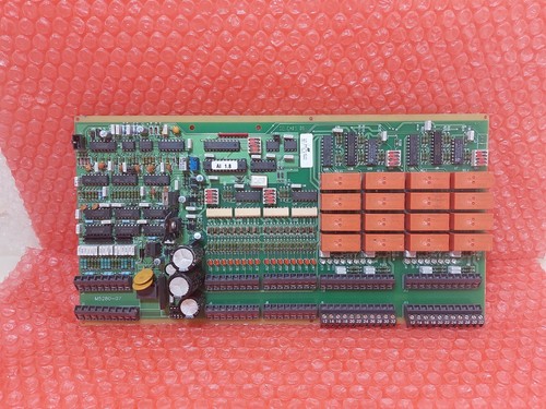
The Vellinge Electronics 560 60 02-01 is an industrial electronic circuit board identified by the PCB number 560 60 02-01 and revision marking K. Additional identification markings include GE CM01.06 and M5280-07.
This board is intended as a replacement spare for equipment using the corresponding Vellinge Electronics assembly. Its exact circuit function and host equipment have not been independently confirmed. Before ordering or installation, compare the complete part number, revision, connector arrangement, and component layout with the original board.
The board is suitable for industrial electronics maintenance, repair work, and spare-parts inventory where matching hardware identification is essential.
Main Functions and Applications
- Industrial electronic PCB assembly.
- Replacement component for equipment using the matching Vellinge Electronics board.
- Supports maintenance of legacy electronic control equipment.
- Provides a board-level spare for repair and equipment restoration.
- Requires verification of host-system compatibility before installation.
Product Parameters
- Brand: Vellinge Electronics
- Main Part Number: 560 60 02-01
- Revision: K
- Additional Marking: GE CM01.06
- Secondary Identification: M5280-07
- Product Name: Industrial Circuit Board
- Product Type: Electronic PCB Assembly
- Application: Host equipment to be confirmed
- Board Function: Not independently confirmed
- Connector Configuration: Verify against the physical board
- Place of Manufacture: Not confirmed
- Product Condition: Verify actual stock condition
- Dimensions: Not confirmed
- Weight: Not confirmed
- Country of Origin: Not confirmed
- Power Requirements: Refer to the host equipment documentation
- Discontinued Status: Current production status not confirmed
Installation and Commissioning
- Verify the complete part number 560 60 02-01 and revision K.
- Check the GE CM01.06 and M5280-07 markings against the original board.
- Compare PCB dimensions, connector positions, component layout, and mounting points.
- Isolate the host equipment from its power supply before removing the original board.
- Use an ESD-safe work area and appropriate antistatic protection.
- Inspect the backplane, connectors, and mating contacts for damage or contamination.
- Install the replacement board in the designated position, following the equipment manufacturer’s procedure.
- Check all connections before restoring power.
- Perform the host system’s approved startup and diagnostic checks.
- Confirm normal equipment operation before returning the system to service.
Do not install this board based only on a similar appearance or partial model-number match.
Daily Maintenance and Care
- Keep the PCB free from dust, moisture, and conductive contamination.
- Inspect connectors and solder joints for corrosion, cracks, or mechanical damage.
- Check for discoloration or signs of overheating around electronic components.
- Maintain adequate ventilation in the equipment cabinet.
- Monitor host-system alarms and diagnostic messages.
- Record the board number, revision, and installation location.
- Store spare boards in sealed antistatic packaging.
Troubleshooting and Common Problems
Problem: Host equipment does not recognize the board
Verify the part number, revision, slot assignment, connector seating, and host-system configuration.
Problem: Intermittent equipment operation
Inspect connectors, solder joints, mounting security, and the host equipment’s power stability.
Problem: Board-related alarm after installation
Check whether the replacement board matches the original hardware revision and configuration. Review the host equipment’s diagnostic information.
Problem: Visible component damage
Inspect for burnt components, cracked solder joints, corrosion, or damaged connectors. Do not energize a visibly damaged board.
Problem: Equipment remains in fault condition
Check associated wiring, power supply, backplane connections, and other system components before concluding that the replacement board is defective.
Safety Precautions
- Installation and servicing should be performed by qualified electronics technicians.
- Disconnect power before handling or replacing the PCB.
- Follow ESD precautions during handling and storage.
- Do not alter components, jumpers, or circuit paths without the correct technical documentation.
- Verify the board’s electrical and mechanical compatibility with the host equipment before commissioning.
Related Vellinge Electronics Models and Parts
The following are additional Vellinge Electronics part-number references. They are not confirmed replacements for 560 60 02-01.
- 560 60 11-01 – PACS 200 Output Module
- 560 60 01-02 – Relay Control Board
- 5606002-01 – Circuit Board / Control Card, MK 87500452-78
For other related models, the host equipment manufacturer and system model should be identified before recommending additional part numbers.